

About the author:
Ricardo Antunes is a first year undergraduate student pursuing a degree in computer science and engineering at Instituto Superior Técnico, Lisboa. Although he is still an undergraduate he has been programming as a hobby since he was 9 years old. He is still trying to find out what his main research interest is.
Recently I’ve contributed to the highgui module through the GSoC program with the addition of the viz3d namespace. So, what are the new features and how can they be used?
Introduction
3D vision has always been a very important part of Computer Vision discipline. Nowadays, with a rapid growth of robotics, self-driven vehicles, virtual & augmented reality and such it’s more relevant than ever. Being able to conveniently play with 3D algorithms and quickly prototype solutions is thus a very important and desirable feature, and OpenCV, as a convenient prototyping solution should offer necessary tools for that.
3D visualization module (called viz) has been a part of OpenCV for several years already, but, unfortunately, it depends on the quite big 3d-party VTK library, which may be tricky to obtain/build on some platforms. Therefore, it was decided to create a light-weight alternative solution that just uses OpenGL together with a native GUI toolkit (e.g. Win UI on Windows or GTK+ on Linux) to display some common 3D objects, such as point clouds, meshes, canonical shapes, camera trajectories etc. This is the goal of this project. The already implemented features include rendering of simple primitives such as cubes and spheres, showing triangle meshes, point clouds and RGB-D images.
How to build it
As opposed to the previous 3D visualization implementation, placed in a dedicated “viz” module in opencv_contrib, this new light-weight API is a part of existing module “highgui”. It has been tested on Windows and should also work on most Linux distributions, as long as you have installed GTK+2 and GTKGLExt. On Ubuntu, building OpenCV with the new Viz3D features requires the following packages:
- libgtkglext1-dev
- libgtk2.0-dev
OpenCV should be configured using the following CMake options:
- WITH_GTK_2_X=ON (only on linux)
- WITH_OPENGL=ON
You can see these features in action with the ‘example_cpp_viz3d’ sample. To build it, you should configure CMake with BUILD_EXAMPLES=ON.
Features
All of the new features are implemented in the cv::viz3d namespace. Every function takes as the first argument the name of the window where the action will take place. Functions that act on objects always take a second argument which specifies the name of the object. For example, if we want to show a red cube at coordinates (5, 5, 5), we can write:
cv::Vec3f red = { 1.0f, 0.0f, 0.0 };
cv::Vec3f green = { 0.0f, 1.0f, 0.0 };
cv::Vec3f blue = { 0.0f, 0.0f, 1.0 };
/*                 window       object     box size              box color */
cv::viz3d::showBox("my window", "cube 1”, { 1.0f, 1.0f, 1.0f }, red);
/*                           window       object     new position */
cv::viz3d::setObjectPosition("my window", "cube 1", { 5.0f, 0.0f, 5.0f });
/* There's also a setObjectRotation */
If you want to show a shaded or wireframe cube, you can set the render mode to RENDER_SHADING or RENDER_WIREFRAME (the default is RIf you want to show a shaded or wireframe cube, you can set the render mode to RENDER_SHADING or RENDER_WIREFRAME (the default is RENDER_SIMPLE),
cv::viz3d::showBox("my window", "cube 2", { 1.0f, 1.0f, 1.0f }, red, cv::viz3d::RENDER_SHADING);
cv::viz3d::showBox("my window", "cube 3", { 1.0f, 1.0f, 1.0f }, red, cv::viz3d::RENDER_WIREFRAME);
cv::viz3d::setObjectPosition("my window", "cube 2", { 0.0f,  0.0f, 5.0f });
cv::viz3d::setObjectPosition("my window", "cube 3", { -5.0f, 0.0f, 5.0f });
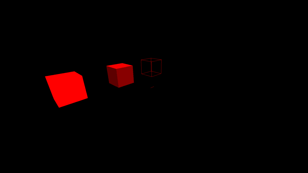
Of course, we’re not limited to boxes, we can also show spheres:
...
cv::viz3d::showSphere("my window", "sphere 1", 1.0f, green);
cv::viz3d::showSphere("my window", "sphere 2", 1.0f, green, cv::viz3d::RENDER_SHADING);
cv::viz3d::showSphere("my window", "sphere 3", 1.0f, green, cv::viz3d::RENDER_WIREFRAME);
cv::viz3d::setObjectPosition("my window", "sphere 1", { 5.0f,  0.0f, -5.0f });
cv::viz3d::setObjectPosition("my window", "sphere 2", { 0.0f,  0.0f, -5.0f });
cv::viz3d::setObjectPosition("my window", "sphere 3", { -5.0f, 0.0f, -5.0f });
And planes:
...
cv::viz3d::showPlane("my window", "plane 1", { 1.0f, 1.0f }, blue);
cv::viz3d::showPlane("my window", "plane 2", { 1.0f, 1.0f }, blue, cv::viz3d::RENDER_SHADING);
cv::viz3d::showPlane("my window", "plane 3", { 1.0f, 1.0f }, blue, cv::viz3d::RENDER_WIREFRAME);
cv::viz3d::setObjectPosition("my window", "plane 1", { 5.0f,  0.0f, 0.0f });
cv::viz3d::setObjectPosition("my window", "plane 2", { 0.0f,  0.0f, 0.0f });
cv::viz3d::setObjectPosition("my window", "plane 3", { -5.0f, 0.0f, 0.0f });
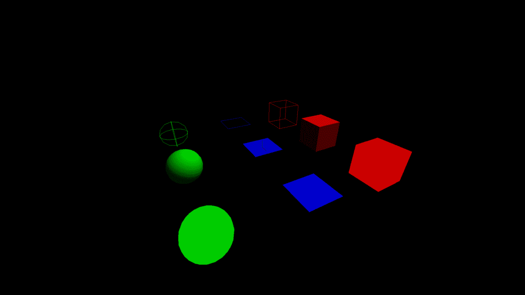
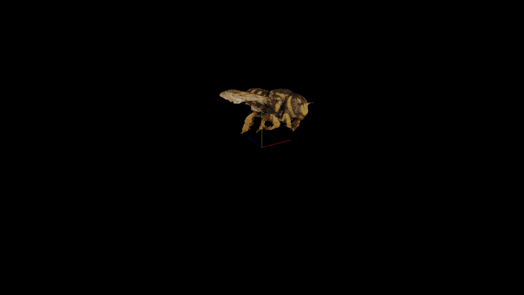
Points clouds can be shown using showPoints or showRGBD. The first function takes as argument a cv::Mat Points clouPoints clouds can be shown using showPoints or showRGBD. The first function takes as argument a cv::Mat containing the point cloud. It must be 2D and have 6 columns, where each row represents a point. The first 3 rows contain the point’s position and the last 3 the point’s color. Here is the code and a bee point cloud shown using showPoints:
cv::viz3d::showPoints(“my window”, “bee”, bee_mat);
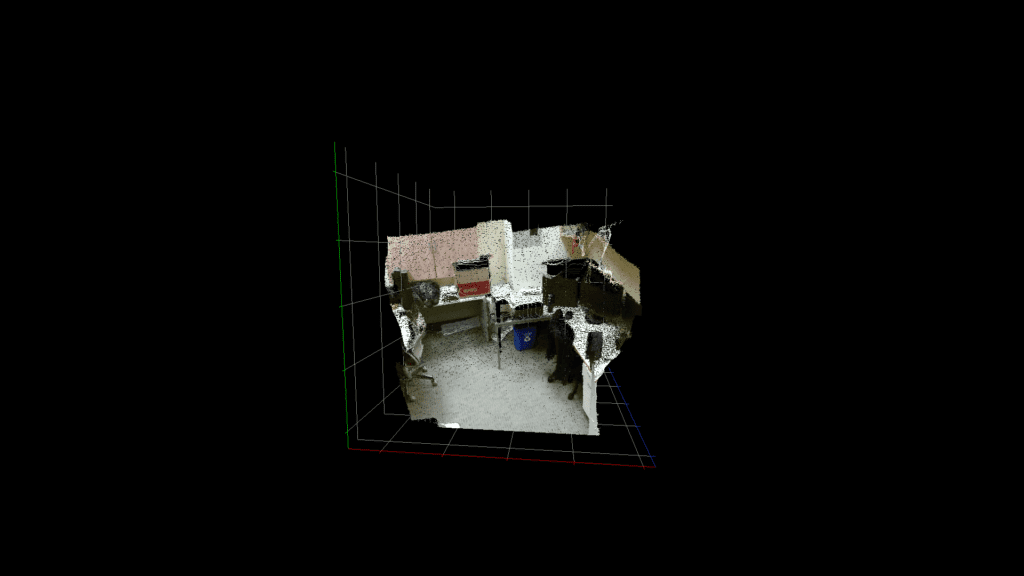
The second function, showRGBD, takes as arguments a cv::Mat which contains an RGB-D image (4 channels) and a camera’s intrinsic matrix and shows the image as a point cloud. In this example, I used setGridVisible to show a grid with a coordinate system instead of a crosshair. I wasn’t able to implement labels yet but I am working on it.
cv::Matx33f intrinsic = {
  529.5f, 0.0f, 365.0f,
  0.0f, 529.5f, 265.0f,
  0.0f, 0.0f, 1.0f,
};

cv::viz3d::showRGBD(“rgbd”,  “points”, rgbd_mat, intrinsic, 0.1f);
cv::viz3d::setGridVisible(“rgbd”, true);
There’s also showLines, which works the same as showPoints but makes each pair of consecutive points a line. showMesh follows the same logic but with triangles instead of points. In showMesh you can choose either to use indices to define the triangles or group vertices 3 by 3. You can also choose to add normals and colors to the input cv::Mat so that the shown mesh is shaded.
Lastly, the camera, lighting and ambient can be configured using setPerspective, setSun and setSky, and objects can be destroyed using destroyObject.
Obstacles
One of the major issues I had was that although the window system already had support for OpenGL rendering, it was very basic and was made with old OpenGL in mind. For example, while the system exposed a setOpenGlDrawCallback function, there was no setOpenGlFreeCallback which would free the objects I needed to allocate for rendering. I ended up extending the windowing system with new functions, such as setOpenGlFreeCallback, getOpenGlUserData.
These new features allowed me to build the viz3d functionality on top of the already existing system. When a viz3d function is called for the first time on a window, an internal object which handles the 3D view and all of the objects on the window is allocated and set using setOpenGlDrawCallback, and later freed by the new OpenGL free callback.
Now I faced a different problem: the OpenCV OpenGL wrapper had no modern functionality implemented (for example, no vertex arrays and no shaders). So I also needed to extend the OpenGL wrapper on the OpenCV core module. I added the Attribute, VertexArray, Shader and Program objects and added new functions for some functionality that wasn’t exposed.
Conclusion
All of the main planned features of this project are already implemented and the only feature missing right now is showing coordinate labels on the axes of the grid. These features make visualizing 3D data on OpenCV easier than ever. Google Summer of Code was my introduction to open source development and I really enjoyed it. It was my first time contributing to a code base as large as OpenCV, and working with people all over the world was a great experience.







5K+ Learners
Join Free VLM Bootcamp3 Hours of Learning