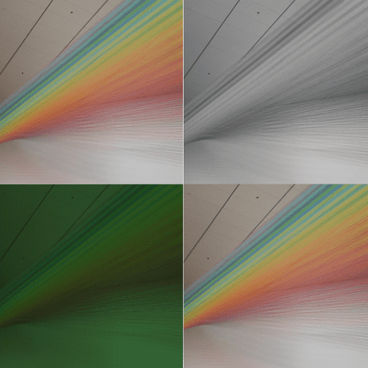
Computer vision engineers often face a hard choice when settling on a sensor module:
Color or grayscale?
On most sensor modules, this is an either/or decision; you can’t have both. This doesn’t appear to be an urgent problem on its surface. Both give visible data, right? Not quite. Color and grayscale each have their own unique characteristics and applications. These qualities should be considered when applying computer vision to any application.
To explore these concepts fully, we must first discuss how grayscale and color cameras are constructed from the CMOS sensor on up; how each pass and process information; and what applications can benefit from each camera modality given these constraints.
For most of this article, I’ll be using this photo I took of Plexus no 36 by Gabriel Dawe at the Denver Museum of Art.
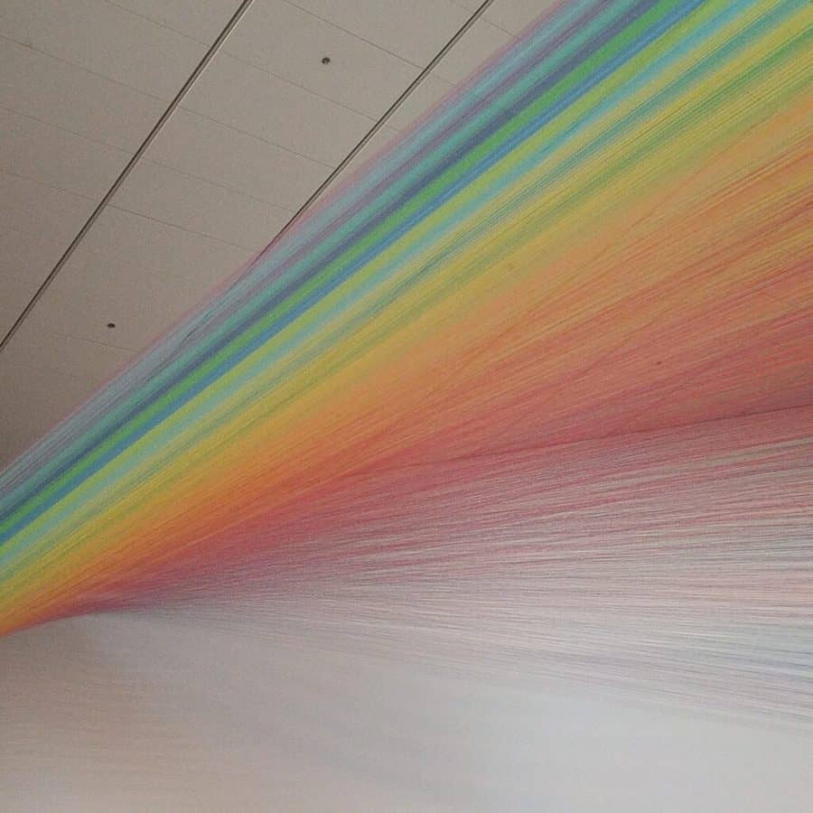
This was taken with the camera on my Google Pixel. Coincidentally, the OAK-D module from OpenCV has the same camera sensor, a Sony IMX378 CMOS chip. This chip has many of the features that we’ll discuss below: Bayer patterns, demosaicing, etc. It performs a lot of pre-processing to make the image as crisp as possible before you ever lay eyes on it, and it does a damn good job.
However, for computer vision engineers (and us at Tangram Vision), it’s worth knowing how it all works under the hood so that we can better exploit the strengths and the weaknesses of different approaches. So, without further ado…
From the CMOS Up
Let’s start at the circuitry. Most consumer-grade cameras use Complementary Metal-Oxide Semiconductor transistors (CMOS) paired with a photodetector to convert photons of light into electronic signals. Each of these individual circuits makes up a pixel; a full grid of these makes a pixel array. What starts as light hitting the array will eventually become an image… but the way that image is created is radically different between grayscale and color sensors.

It’s important to note that a pixel array won’t react to all incoming light. Rather, it only responds to a certain spectrum of light wavelengths. For our discussion, this is the visible light spectrum with wavelengths from 380nm (violet) to 750nm (red).
When light from this spectrum hits a pixel well on the CMOS sensor, it creates a response proportional to the luminance, aka the light’s intensity per unit area. This response triggers an electrical signal on the sensor that produces a “brightness” value. The aggregation of all these values creates what we know of as a grayscale image!

Making the Jump to Color
Notice that, right now, this sensor only measures one thing: the luminance of the visible light hitting that pixel. This will therefore give us only one value for each pixel. This won’t do for color, since what we know of as “color” is the selective combination of three different visible wavelength spectra: red, green, and blue. Humans are able to do this using cellular light filters in the eye known as cones, which break white light into component parts of long wavelength (red), medium (green), and short (blue). These components are then processed by the brain into the colors we see.
Likewise, any sensor that processes color data should do something similar. The most common way to do this with a CMOS sensor is to cover the pixel wells with a color filter array (CFA). This is a layer placed over the sensor that covers each pixel with a red, green, or blue light filter. Now, light entering the pixel no longer travels unhindered! Instead, the wave is broken apart, and only the spectrum that matches that chosen filtered wavelength makes it through.
Now, when we take a picture with this CFA-covered CMOS, we get our color components… but that by itself won’t be enough. See for yourself:
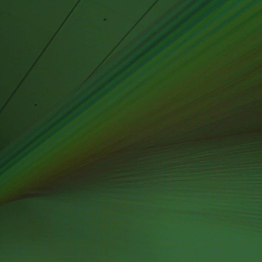
Let’s zoom in a bit on that “color” image that the sensor captured above:
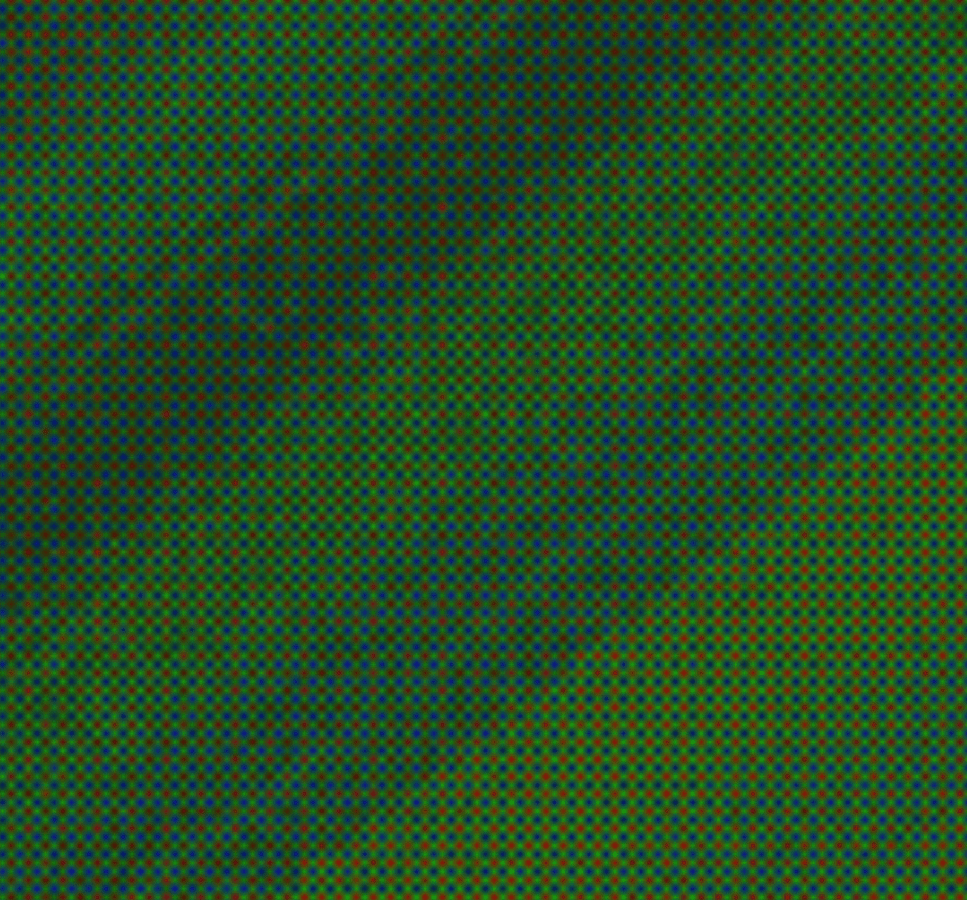
Doesn’t look quite right, huh? This is our first big (albeit obvious) difference between color and grayscale: the two modalities measure different information across the same spectrum. In the case of a sensor with a CFA, even different pixels measure different information! This is also our biggest issue when using color cameras for computer vision; we’ll see why once we understand how color is derived.
Color Filter Arrays
Each pixel on the color sensor only has a fraction of the information needed, e.g. a pixel will only have the red “R” component of an RGB color! This component is called a sensel, being the smallest piece of sensor information possible from our CMOS. We’ll need all R, G, and B sensels together to recreate the true color of the pixel. Where do we get the green “G” and the blue “B” sensels? How do we combine this information to recreate the true color?
There are plenty of answers to these questions, all with their own tradeoffs and advantages. The key lies in the color pattern used in the CFA. Most off-the-shelf color cameras use a CFA called a Bayer pattern. Here, every 2×2 pixel patch has two green filters, a red filter, and a blue filter. Both the medium and long-wavelength cones in human eyes are sensitive to green light, so green is represented twice as much in a Bayer filter to mimic this effect. Bayer patterns can be found in BGGR, RGGB, and GRBG variants, all of which are named by reading the pattern row-wise from the top.

Beyond Bayer
Despite its ubiquity, the Bayer pattern isn’t perfect. Since the green filter of a Bayer pattern only registers half of the image (2 out of every 4 pixels), and the red and blue filters only a fourth of the image (1 of every 4 pixels), important color information is actually thrown out before it can be used. This is the reality for most all CFAs, as the very act of filtering color removes information. Different filter styles use different patterns in order to compensate for different things. A few examples:
- RCCC: Red-clear-clear-clear. This is a filter for the automotive industry; red is a warning on the road, so its color information is the only one that matters.
- RGBE: Red-green-blue-emerald. Emerald here is a cyan-like pigment.
- CYYM: Cyan-yellow-yellow-magenta. While RGB are the primary colors of light, these are the primary colors of pigment.
- X-Trans: An RGB filter used by Fujifilm, developed to minimize moire pattern generation (more on that below).
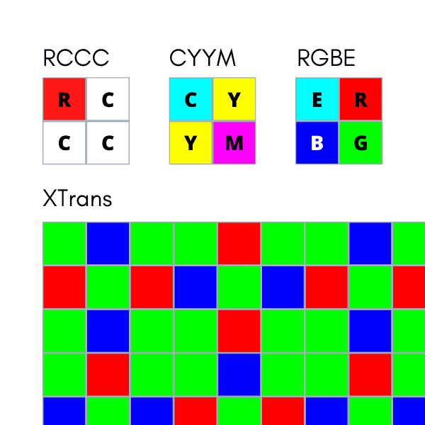
…and the list goes on. Regardless of filter type, all CFAs listed above suffer from the same problem as the Bayer pattern: a pixel will only ever contain a part of the true color. It’s up to us to derive the true color any way we can. This process is called demosaicing.
Demosaicing
There’s no “correct” method of demosaicing a Bayer pattern. They all seek to replicate what the human eye would see, but the information lost using a CFA prevents any method from creating color that’s 100% true-to-life.
The most basic way to demosaic is to just take the values of the closest sensels and create an RGB color.
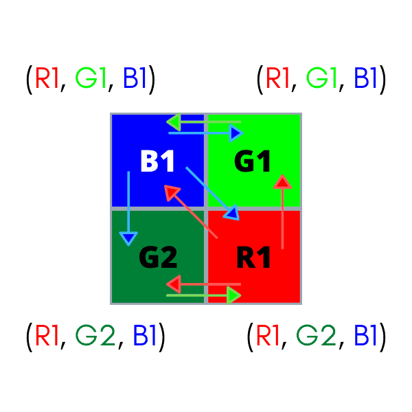
This is called nearest-neighbor interpolation, and it is a definitively bad way to reconstruct color. Let’s use nearest-neighbor interpolation on our checkered Bayer pattern image:
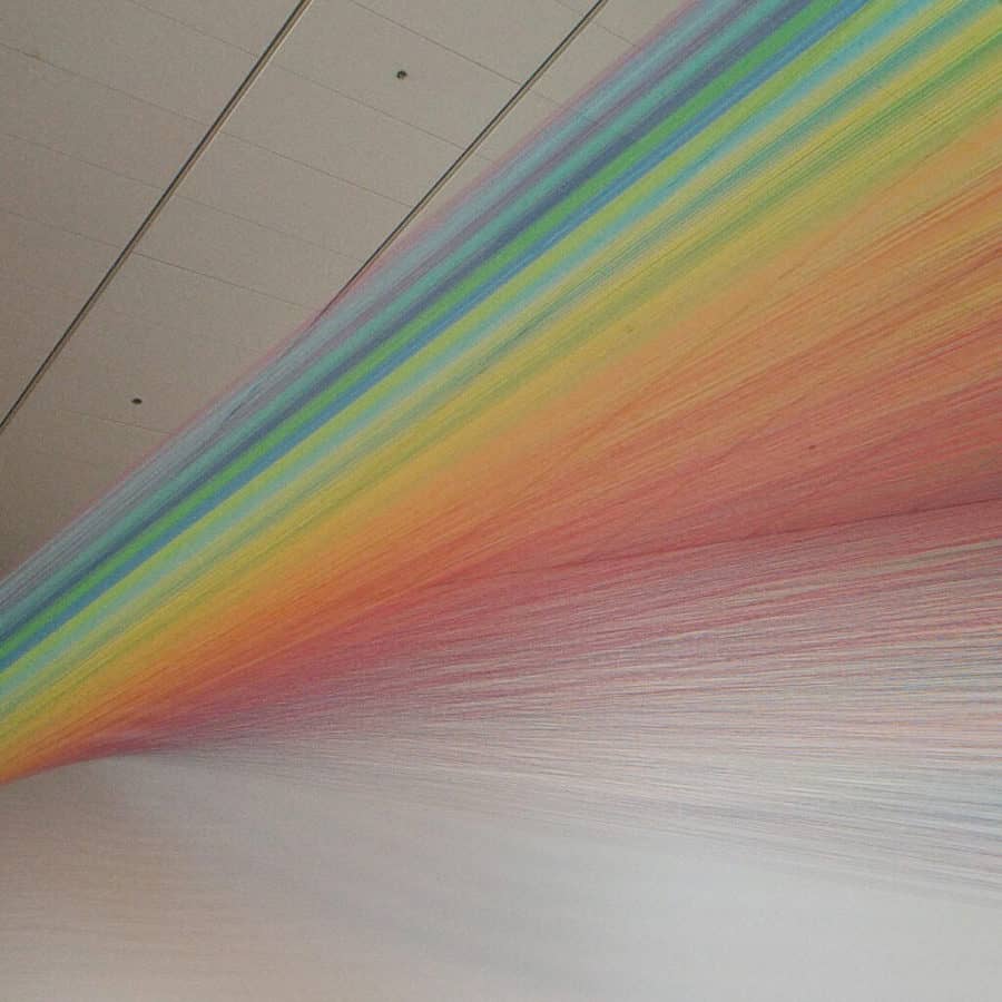
Not bad… but it’s not good. It might look fine from here, but let’s compare it to our control image from the beginning of this article:
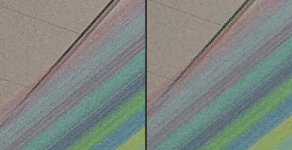
See those jagged edges and blurred color transitions? That’s no good! We can be smarter than that. Many demosaicing algorithms are designed to take more information into account, like pixels farther away or areas of similar values, in order to make more intelligent decisions about color composition. The demosaicing method used can make a huge difference in color image quality. A good discussion of different methods and their effects can be found here.
Demosaicing Dangers
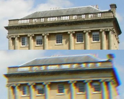
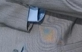
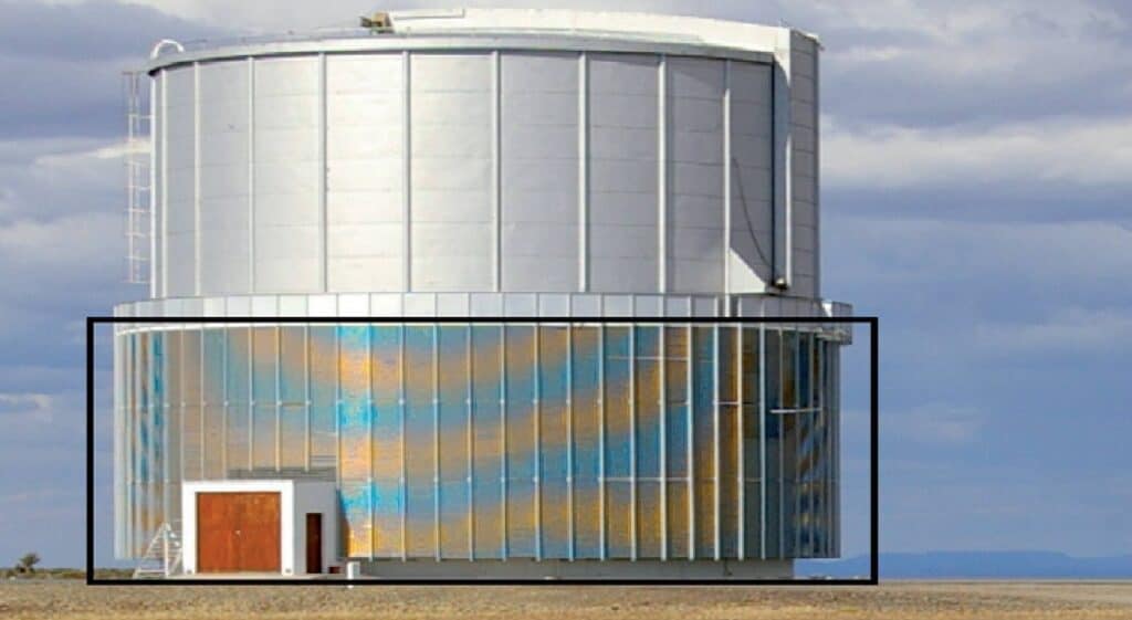
Unfortunately, even the best demosaicing algorithm can still introduce all sorts of undesired artifacts into an image. Here are just a few:
Chromatic aberration – Color blurring, normally exhibited at sharp edges or discontinuities in the image. Caused by poor sensel interpolation across sharp color boundaries.
Moire effects – Overlapping patterns that create interference between themselves. Happens often when capturing electronic screens. Normally paired with false coloration.
False coloration – Another victim of poor sensel interpolation. This happens when a demosaicing algorithm factors in the wrong pixels for a certain area.
Notice that we haven’t discussed grayscale cameras in a while? That’s because they don’t have to worry about any of this! There’s no pre-processing of pixel values; no algorithmic worries; no CFA decisions. It’s just straightforward pixel measurements, aggregated and sent as an image. This means that grayscale cameras don’t suffer from any of the side effects of demosaicing. What you see is what you get, and you get it fast.
Grayscale Wins
This attribute is one of the best features of grayscale imaging, and it is the primary reason why grayscale is preferred in high-speed and high-performance applications. The information that one receives is clean, simple, and delivered quickly.
That last point about getting useful data quickly is a big one. Many tracking and mapping pipelines are bottle-necked by the data throughput of the device to the host, so let’s compare the data throughput of grayscale vs color imaging given standard USB 2.0 transmission rates. We can do some back-of-the-napkin math to see the effects of our camera choice on this important metric:
With USB 2.0 transmission (capped at 60MB/s):
✅ Grayscale VGA at 30 fps: 9.2MB/s
✅ Grayscale 720p at 30 fps: 27.6MB/s
✅ Color VGA at 30 fps: 27.6MB/s ← but this could still hurt our pipeline!
❌ Color 720p at 30 fps: 82.9MB/s ← not a chance.
How can color hurt our vision pipeline? Well, if we use color at a high resolution, we are forced to drop the frame rate to at least 15 fps (if not more). Even once we compensate for the data overload, we might still receive an image suffering from blurring or moire effects, and that will negatively affect our computer vision system. Bottom line: if an application relies on sharp features and fast frame rates to keep operating smoothly, then color might not be the best option. Opt for a grayscale sensor in order to achieve the right performance metrics.
How did we get these numbers?
Grayscale: A grayscale image describes each pixel value with 8 bits of information. Multiply this by 640×480 (the pixel resolution of a VGA image) and send that amount of information 30 times every second (a common frame rate for many applications). We’re now looking at 73,728,000 bits of information per second, i.e. 9.2MB/s. That’s not bad; USB 2.0 can handle 60MB/s, so we’re looking good. Even if we pumped that up to 1280×720 (720p), we only hit 27.6MB/s, which is well within the theoretical threshold.
Color: Once an image undergoes demosaicing, each pixel carries its full RGB color information. This means we have three 8-bit values every pixel, not just one. Doing the same math as above for a VGA image, we’re hitting 27.6MB/s already. Make that a 720p image, and we’re up to 82.9MB/s, which is WAY over the USB 2.0 threshold of 60MB/s.
…but Color Wins, too
We’ve already seen that color data costs more, both computationally and data-wise, but it can be worth it under the right circumstances. Specifically, the addition of color provides new and exciting ways to infer semantics.
We as humans usually aren’t thinking about geometry; we’re often more preoccupied by colors or materials, figuring out how we might interact with a scene and its objects. These are all known as the semantics of a scene. For instance, humans rely on color information to tell if a certain snake is venomous or a certain berry is edible, not just shape. Computers can use this information the same way humans can, to the same effect.
As one can imagine, classifiers and neural networks also do better with more data. What better way to produce data than to provide three times the amount of information per pixel? On top of that, grayscale data can be calculated by using common RGB→Grayscale conversions. This allows networks to use both RGB and luminance values with just a little more computation.
Of course, the color image problems that we explored above still exist. Producing clean and consistent color data is always a challenge! Getting it right can be a chore, but the reward is a rich store of data that can boost a vision system in powerful ways. For all the other times when geometry and speed matter most, grayscale systems are there to provide.
In many cases, robotic system design can benefit from the use of both grayscale and color images. But if you thought this was complicated, you ain’t seen nothing yet! A whole host of additional sensor challenges emerge in multi-sensor situations like this, such as calibration and proper sensor fusion. These kinds of challenges are what we address at Tangram Vision. We’re working to illuminate some of those challenges for the entire Robotics and CV community, and we’ll be back to keep doing the same here!
If you want to try this out for yourself, visit the GitLab repository for the Tangram Vision Blog. Were uploaded the code samples we created to make these images. Contributions always welcome!

Brandon Minor
CEO and Co-founder, Tangram Vision
Brandon Minor is Co-Founder and CEO of Tangram Vision. Tangram Vision creates the Tangram Vision SDK, which provides tools to streamline adding and managing perception sensors like LiDAR, depth, CMOS and IMU to sensor-enabled platforms like robots, drones and autonomous vehicles.




5K+ Learners
Join Free VLM Bootcamp3 Hours of Learning